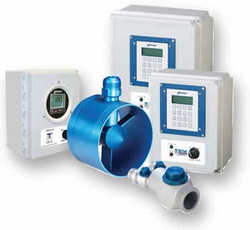
SPECIFICATION OF BI-FUEL SYSTEM
The bi-fuel system shall…

1. Allow the converted generator to operate on a mixture of diesel fuel and
natural gas, or alternately, on 100% diesel fuel.
2. allow for a minimum of 50% and a maximum of 70% gas substitution at
the engine prime rating. In the event that 50% gas substitution cannot be
achieved due to poor gas quality, engine condition, knock limits,
temperature limits, etc., the system shall be capable of supplying the
maximum possible gas substitution in keeping with safe engine operation.
3. be a retrofit-type technology that allows the generator to be converted onsite.
4. allow the generator to be manually or automatically switched between fuel
modes with no loss in generator performance or drop / interruption in
power output.
5. not require that the generator be taken off-line for installation.
6. not require that any changes be made to the generator drive engine,
including but not limited to changes in engine compression ratio, piston
design, valve timing, injection timing, fuel system design, cylinder head
design, etc. Further, installation of bi-fuel system shall not require removal
of cylinder heads, valve covers, adjustment of valve train or adjustment or
replacement of diesel injectors.
7. not require drilling and tapping of engine intake / exhaust manifolds, or
drilling and tapping of engine cylinder heads.
8. be able to operate on low pressure natural gas with a delivery pressure at
the generator skid of between 2-5 psi.
9. meet or exceed 100% diesel transient load performance while operating in
bi-fuel mode.
10. meet OEM requirements for engine operating parameters including:
a. exhaust gas temperature
b. engine coolant temperature
c. intake manifold temperature
d. lube oil temperature
e. aftercooler / intercooler temperature
f. diesel fuel temperature
g. compressor inlet restriction
11. include a complete “gas train” consisting of at least the following minimum
items:
a. 50 micron in-line gas filter
b. normally closed / DC operated gas solenoid valve with dual,
redundant shutoff valves
c. “Zero Governor” type gas regulator
12. utilize gas train components which are approved or certified by each of the
following organizations:
a. CGA
b. CE
c. UL
d. FM
13. utilize materials and component construction suitable to the media,
temperatures, vibration and duty cycles which the component is subjected
to during normal operation of the generator.
14. utilize threaded, JIC type connections between the gas train and air-gas
mixers.
15. shall include properly rated, flexible fuel delivery hoses with female JIC
swivel connections for connecting the air-gas mixers and gas train.
16. utilize a master control panel installed in an area adjacent to the
generator. The master control panel shall control the bi-fuel system and
have the following minimum design features:
a. NEMA 4X rated enclosure
b. Microprocessor based controller
c. CSA rated for Class I Div II
d. 24 VDC
e. readily visible LED lights showing normal and fault modes
f. LCD display showing current status of bi-fuel system /
monitored channels
g. hour meter displaying total time accumulated in bi-fuel mode
h. manual start-stop switch
i. key-pad user interface for selecting monitored channels and
entering safety setpoints and control setpoints.
j. Electronically calibrated sensors
17. utilize a control system that monitors at least the following engine / system
parameters:
a. exhaust gas temperature for each turbo
b. manifold air temperature
c. natural gas supply pressure to gas train
d. natural gas supply pressure from gas train to engine
e. engine manifold air pressure
f. engine vacuum for each air-intake
g. engine vibration level – right and left banks
18. at all times during bi-fuel operation monitor critical engine parameters; the
user shall be able to set the maximum or minimum allowable limits for on
a discrete basis for each channel.
19. at all times during bi-fuel operation monitor natural gas supply pressure
and be able to detect a drop or increase in natural gas pressure.
20. at all times during bi-fuel operation monitor engine manifold air pressure
(turbo boost pressure) as a control setpoint; user shall be able to select a
low MAP setpoint and high MAP setpoint delineating the engine load
window for bi-fuel operation. The user shall be able to set the maximum
and minimum allowable pressures. Engine manifold air pressure shall be
monitored via a pressure transducer using a weather-proof type wire
connection.
21. at all times during bi-fuel operation monitor engine vibration level in order
to detect improper combustion (knock). User shall be able to set vibration
safety limits to within .10 inch per second (IPS) from normal engine
vibration levels at rated load.
22. have been installed on at least 100 MW (megawatts) of power generating
sets within the previous two (2) years. Documentation detailing
installation history shall be provided on request.
23. have accumulated at least 20,000 hours of operation in either prime,
stand-by or peak shaving use. Documentation detailing operational
history shall be provided on request.